Introduction
Learning quantum computing basics can feel like trying to read a completely foreign language. When you first encounter terms like superposition, entanglement, and quantum algorithms, the theory can quickly become overwhelming. Thankfully, you do not have to rely solely on complex mathematical equations to understand how quantum computers process information. Visual tools bridge the gap between abstract quantum physics and practical software engineering. Quantum circuit diagrams serve as a universal blueprint for quantum programming. They turn invisible quantum states into clear, step-by-step visual roadmaps. By learning how to read these diagrams, you can easily track how information flows through a quantum system. If you are looking for a structured environment to build these foundational skills, QuantumOpsSchool.com provides excellent educational resources tailored for beginners, students, and software developers alike.
What Is a Quantum Circuit?
Featured Snippet Definition: A quantum circuit is a visual representation of a sequence of quantum operations performed on qubits to execute a specific quantum algorithm. Unlike classical circuits that use copper wires and silicon transistors, a quantum circuit is a conceptual diagram showing how quantum information changes over time.
          +---+     +---+     +M|
|0> ------| H |-----| X |-----[M]=== (Classical Output)
          +---+     +---+     +M|
The primary purpose of a quantum circuit is to map out the life cycle of a quantum computation. It provides an intuitive layout that helps developers, students, and engineers understand how a quantum algorithm manipulates data.
Instead of writing out long strings of linear algebra, you can look at a circuit diagram and instantly see which quantum gates are being applied and when.
In the early stages of beginner quantum computing, these diagrams act as your primary learning aid. They break down complex quantum phenomena into sequential, digestible actions. This visual approach is crucial for building a solid mental model before you start writing code in quantum programming frameworks.
Core Components of a Quantum Circuit
To read a quantum circuit diagram smoothly, you must first become familiar with its foundational building blocks. Every circuit, no matter how complex, relies on a few standard visual symbols.
Qubits
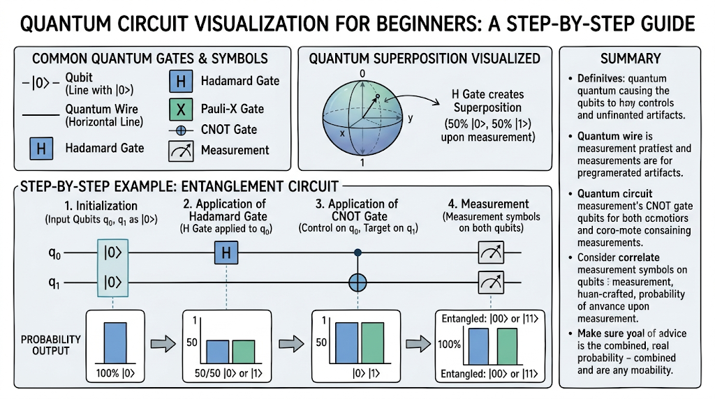
A qubit (quantum bit) is the fundamental unit of quantum information. In a circuit diagram, each qubit is represented by a horizontal line. The line does not represent a physical wire, but rather the timeline of that specific qubit as the program runs. Qubits usually start on the far left in a default baseline state, typically written as $|0\rangle$.
Quantum Wires
The horizontal lines stretching from left to right are called quantum wires. They represent the passage of time and the preservation of the qubit’s state between operations. Data travels from left to right along these wires.
Quantum Gates
Quantum gates are the operational blocks placed along the quantum wires. They are usually represented by square boxes containing a letter (such as X, H, or Z) or distinct geometric symbols. Each gate alters the state of the qubit it sits on, performing mathematical transformations visually.
Measurement Symbols
The measurement operation is represented by a box containing a meter dial symbol or a simple “M”. This symbol indicates the point where the quantum world meets the classical world. Measuring a qubit forces it out of its fluid quantum state and locks it into a permanent classical value.
Circuit Flow
Circuit flow always moves strictly from left to right. The leftmost side represents the initialization phase, the middle section displays the step-by-step gate operations, and the rightmost side contains the final measurements.
Classical Output
Once a measurement occurs, the quantum wire transforms into a classical wire, which is traditionally drawn as a double parallel line. This double line carries the final binary data (a 0 or a 1) to your standard computer screen.
Quantum Circuit Visualization for Beginners
Reading Quantum Circuit Diagrams
Reading a circuit diagram is very similar to reading a sheet of music. Each horizontal line represents an instrument (a qubit), and the notes placed along the lines are the instructions (quantum gates) that tell the instrument what to do over time. You read the diagram chronologically, starting from the left and moving toward the right.
Understanding Circuit Direction
Because time flows from left to right, any gate placed further to the left happens before a gate placed to the right. If two gates are stacked vertically on top of each other on different lines, it means those operations are happening simultaneously.
Multi-Qubit Circuits
When an algorithm requires more than one qubit, multiple horizontal lines are stacked vertically. This layout allows gates to span across multiple wires, demonstrating how qubits interact with one another to share information or create quantum entanglement.
Measurement Operations and Interpreting Results
When a qubit passes through a measurement box, its quantum properties disappear. The result is a simple classical bit. Because quantum physics is inherently probability-based, running the exact same circuit multiple times might yield different outcomes. Visualizing the circuit helps you understand where these probabilities are created and where they are finally recorded.
QuantumOpsSchool.com Guide to Quantum Circuit Visualization
Learning Circuit Fundamentals
At QuantumOpsSchool.com, the learning methodology focuses on breaking down the abstract nature of quantum physics into clear, visual workflows. For beginners, trying to memorize the mathematics behind a quantum state can be discouraging. By using intuitive visual guides, you learn to see how information shifts before dive-testing the equations.
Understanding Gate Operations
Instead of looking at complex matrix multiplications, the QuantumOpsSchool.com approach encourages students to view gates as simple interactive switches. For example, visualizing a gate as a mechanism that flips a switch or spins a globe makes the learning process natural, memorable, and highly engaging.
Building Simple Quantum Circuits
The ideal path for any beginner is to start by manipulating a single qubit. You can visualize a single wire, drop a gate onto it, and look at the predicted output. Once you are comfortable with how a single line behaves, you can confidently introduce a second wire to observe how data paths cross.
Visualizing Quantum Algorithms
As you advance, you will encounter complete quantum algorithms. These are simply larger collections of gates arranged in specific patterns to solve complex problems. Visualizing these algorithms as modular blocks allows you to understand the big picture without getting lost in the underlying programming syntax.
Strengthening Quantum Computing Skills
Mastering circuit diagrams changes the way you write code. When you use a quantum simulator or write software in a real development framework, your mind will automatically visualize the circuit structure. This mental clarity leads to cleaner code, fewer design mistakes, and faster development cycles.
Common Quantum Gates
To build and read circuits effectively, you must learn the visual vocabulary of the most common quantum gates.
   +---+        +---+        +---+        ---+---        ---X---
---| X |---  ---| H |---  ---| Z |---        |          |
   +---+        +---+        +---+        ---+---        ---X---
  Pauli-X      Hadamard     Pauli-Z         CNOT          SWAP
Pauli-X Gate
The Pauli-X gate is the quantum equivalent of the classical NOT gate. It is represented by a box marked with an “X”. Its educational significance is straightforward: it flips a qubit’s state. If a qubit is in state $|0\rangle$, the X gate flips it to $|1\rangle$, and vice versa.
Hadamard Gate
The Hadamard gate, represented by an “H” box, is the gateway to quantum superposition. It takes a definite state (like $|0\rangle$) and puts it into an even blend of both 0 and 1 at the same time. Visually, it represents the exact moment a circuit transitions from classical logic into true quantum mechanics.
Pauli-Z Gate
The Pauli-Z gate appears as a box marked with a “Z”. Instead of flipping the qubit’s basic value, it flips its phase. Think of it as altering the direction a wave is pointing without changing the size of the wave itself. It is widely used to control how paths interfere with each other in quantum algorithms.
CNOT Gate
The Controlled-NOT (CNOT) gate is a multi-qubit gate represented by a small filled circle on one wire (the control qubit) connected by a vertical line to a larger target symbol (a circle with a plus sign) on another wire. It flips the target qubit only if the control qubit is active. This gate is fundamental for creating quantum entanglement.
SWAP Gate
The SWAP gate is used to exchange the states of two distinct qubits. It is visually represented by two small “X” symbols on different wires connected by a vertical line. This operation is highly important when working on physical quantum hardware where qubits can only talk to their immediate neighbors.
Measurement Operation
The measurement operation is your exit window from the quantum environment. It tells the reader exactly where the quantum calculation stops and where the data conversion to standard binary numbers begins.
Benefits of Circuit Visualization
- Easier Concept Understanding: Seeing a concept visually is much easier than trying to decipher long rows of abstract mathematical symbols. Diagrams make quantum logic accessible to everyone.
- Better Algorithm Design: When you map out your program visually, you can easily spot design patterns, structure your logic steps cleanly, and optimize how your gates are ordered.
- Simplified Debugging: Looking at a visual timeline makes it much easier to spot an misplaced gate or an incorrect wire connection that might be ruining your calculations.
- Improved Learning Experience: Visual feedback keeps you engaged. It transforms quantum computing from a theoretical math exercise into an interactive, creative design process.
- Stronger Quantum Programming Skills: A strong visual understanding makes it much easier to transition between different software development toolkits, as the underlying circuit design rules remain exactly the same.
Classical Logic Diagrams vs Quantum Circuit Diagrams
Understanding the differences between classical computing diagrams and quantum circuit diagrams helps clarify why quantum systems are so uniquely powerful.
| Feature | Classical Logic Circuits | Quantum Circuits |
| Basic Unit | Bit | Qubit |
| Operations | Logic Gates (AND, OR, NOT) | Quantum Gates (H, X, CNOT) |
| State Representation | Strictly Binary (0 or 1) | Quantum States (Superposition) |
| Parallelism | Limited to physical hardware paths | Exponential via Superposition |
| Output | Deterministic (Same input always gives same output) | Probability-Based (Results are statistical averages) |
Common Challenges and How to Overcome Them
Understanding Circuit Symbols
- The Challenge: Memorizing all the different gate symbols and line types can feel overwhelming at first glance.
- The Solution: Focus on mastering just three primary gates first: the X gate, the H gate, and the CNOT gate. The rest can be learned gradually as you need them.
Visualizing Superposition
- The Challenge: It is difficult to visualize a qubit being in multiple states simultaneously along a single flat line.
- The Solution: Use the “coin spin” analogy. A flat coin is either heads or tails (a classical bit), but a spinning coin is a blend of both states at once (superposition). The wire simply tracks that spinning coin.
Reading Multi-Qubit Circuits
- The Challenge: When diagrams feature many horizontal lines and crossing vertical lines, tracking the operations can get confusing.
- The Solution: Use a piece of paper or a digital pointer to cover up everything except one single time step. Read the circuit column by column, from left to right.
Measurement Concepts
- The Challenge: Understanding why a qubit changes its behavior completely after a measurement box can be confusing.
- The Solution: Remember that measurement is an active look into a delicate system. Think of it like opening a box to stop a spinning top; looking forces the action to stop and settle into a static position.
Learning Quantum Gates
- The Challenge: Believing you need an advanced physics degree to understand what gates are actually doing inside a circuit.
- The Solution: Treat gates like modular logic blocks. You do not need to build a physical engine to understand how to drive a car; similarly, you only need to understand what a gate outputs, not the complex physics behind it.
Best Practices for Beginners
- Start with one-qubit circuits: Resist the temptation to jump into large, multi-qubit systems. Master single-wire operations completely before adding more complexity.
- Learn common gate symbols first: Build a strong foundation by making a simple reference sheet of core gates (H, X, Z, CNOT) to use while reviewing diagrams.
- Practice reading circuit diagrams daily: Spend five minutes every day tracing the flow of a simple circuit diagram from left to right to build visual familiarity.
- Use quantum simulators for visualization: Pair your reading with open-source drag-and-drop quantum simulators. Moving gates around on a screen and watching the results update in real-time reinforces your learning.
- Build increasingly complex circuits gradually: Once you completely understand a two-qubit system, challenge yourself by adding a third wire or introducing a new gate operation.
Career Opportunities
- Quantum Software Developer: Writes the programmatic code that translates visual circuit designs into functioning quantum software applications.
- Quantum Computing Engineer: Designs, runs, and optimizes the practical configurations of quantum circuits on real computing systems.
- Quantum Algorithm Developer: invents new sequences of quantum gates to solve complex computational problems more efficiently than classical computers.
- Quantum Research Scientist: Investigates new ways to arrange circuits, control error rates, and discover unique quantum states.
- Quantum Systems Engineer: Bridges the gap between software instructions and physical hardware control lines to ensure circuits run smoothly.
- Quantum Application Developer: Focuses on using pre-built quantum circuits to solve real-world problems for industries like logistics, finance, and chemistry.
Future of Quantum Circuit Visualization
Interactive Visualization Tools
As the field grows, we are moving away from static images toward highly interactive, web-based circuit editors. These tools let developers watch changes in quantum states happen live as they drag gates across wires.
AI-Assisted Quantum Programming
Artificial intelligence will soon assist in optimizing circuit designs. AI assistants will analyze your visual layout and suggest cleaner arrangements, helping to minimize errors and reduce the number of required gates.
Cloud-Based Quantum Development
More platforms are moving their visualization tools completely to the cloud. This shift allows you to design a circuit visually in your web browser and send it directly to a real quantum computer located halfway around the world.
Advanced Quantum IDEs
Integrated Development Environments (IDEs) are becoming increasingly visual. Instead of separating your text code from your circuit diagrams, future tools will show your code and your visual circuit side-by-side, updating both automatically as you work.
Enterprise Quantum Applications
As businesses adopt quantum technology, visual diagrams will become the primary way technical leaders explain quantum workflows to project managers, clients, and stakeholders.
Common Misconceptions
Circuit Diagrams Show Physical Hardware
A very common misconception is that the horizontal and vertical lines in a diagram represent actual physical wires inside a quantum computer. In reality, they are purely conceptual timelines showing what happens to a qubit over time.
Bigger Circuits Always Produce Better Results
Adding more qubits and gates does not automatically make a quantum program more powerful. In fact, because current quantum systems are prone to environmental noise, keeping your circuits as small and simple as possible usually delivers much better results.
Visualization Replaces Quantum Theory
While visualization tools are incredibly helpful for learning, they work alongside theory rather than replacing it entirely. Visual layouts give you an intuitive understanding, which makes diving into the underlying math much easier later on.
Beginners Must Learn Advanced Mathematics First
You do not need to master complex linear algebra or quantum mechanics before you can start learning circuit designs. Visual tools allow you to learn the practical logic of quantum computing first, letting you save the deeper mathematics for down the road.
FAQ Section
- What is the primary direction of flow in a quantum circuit diagram?
Quantum circuit diagrams are always read chronologically from left to right. The leftmost part of the diagram shows the starting setup of the qubits, the middle section displays the gates being applied over time, and the rightmost part shows where the final measurements occur.
- Can a beginner learn quantum programming using just visual circuit diagrams?
Yes, absolutely. Visual circuit diagrams are the best entry point for beginners because they remove the initial barrier of complex mathematics. They allow you to learn the foundational logic of how qubits change state before you ever have to write text-based code.
- What does a double horizontal line mean at the end of a quantum circuit?
A double horizontal line represents a classical wire. It carries standard binary information (a 0 or a 1) that is produced after a qubit passes through a measurement box, taking the data out of the quantum environment and into a format your everyday computer can read.
- Why do quantum gates look like simple boxes with letters inside them?
They are designed as simple labeled boxes to make diagrams clean and easy to scan. The letter inside the box tells you exactly which mathematical operation is being applied to that qubit, allowing you to trace the logic of the system without cluttering the page.
- What is the difference between a classical gate and a quantum gate?
A classical gate takes definite inputs (like 0 and 1) and outputs a fixed result based on traditional logic rules. A quantum gate manipulates fluid quantum states, allowing for advanced operations like superposition and entanglement that classical systems cannot replicate.
- How does a beginner practice building quantum circuits without real hardware?
You can use free, web-based quantum simulators that offer intuitive drag-and-drop interfaces. These tools allow you to build circuits visually, run simulations instantly, and see exactly how your choices affect the final output in real-time.
- What is the purpose of the Hadamard gate in a visual diagram?
The Hadamard gate is used to put a qubit into a state of quantum superposition. In a circuit diagram, it marks the exact point where a qubit moves from a definite starting value into an even blend of both 0 and 1 simultaneously.
- Do I need to memorize all quantum gates to get started?
No, you do not. You only need to learn a few core operations to begin, such as the Pauli-X gate, the Hadamard gate, and the CNOT gate. Once you understand how these three work together, adding new gates to your vocabulary becomes very easy.
- Why do we need measurement symbols in a quantum circuit?
Quantum computers must eventually output standard data that humans can read. The measurement symbol shows exactly where a qubit’s delicate quantum state is stopped and recorded as a permanent, classical binary number.
- How do multi-qubit gates appear on a circuit diagram?
Multi-qubit gates are drawn as vertical lines that connect two or more horizontal qubit wires. This layout shows you exactly which qubits are interacting with each other, making it easy to see where operations like quantum entanglement are taking place.
Final Summary
Mastering quantum circuit visualization for beginners is one of the most rewarding steps you can take on your quantum computing journey. By shifting your focus from dense mathematical equations to clear, visual timelines, you can build an intuitive understanding of how qubits, quantum gates, and circuit flows interact. These visual blueprints turn abstract theories into structured, logical pathways, giving you the clarity needed to explore quantum algorithms with genuine confidence.
As you continue to build your skills, remember that consistent practice with foundational concepts is the key to long-term success. Educational platforms like QuantumOpsSchool.com are designed to support you every step of the way, offering structured learning paths that make advanced technology accessible and rewarding. Embrace the visual learning process, use interactive simulators to experiment, and you will quickly find yourself designing and reading quantum circuits with ease.